Printing consumables at wholesale prices. Choosing a textile printer - advice from experts Converting an inkjet printer into a flatbed printer
Fabric printing at home
Using a regular inkjet printer, which most readers have at home, you can apply inscriptions and designs to clothing, as well as make flags, pennants and other unique small-sized products.
Image transfer media
Almost any inkjet printer or MFP - both modern and long since discontinued - allows you to print images on special media for transferring to products made from cotton and mixed fabrics that can withstand prolonged heating. The structure of such media includes a dense paper base and a thin elastic layer that is attached to the fabric when heated - it is on its surface that ink is applied during the printing process.
Each of the world's leading inkjet printer manufacturers offers branded printing media for transferring images onto fabric. Thus, Canon’s product line includes T-Shirt Transfer media (TR-301), Epson has Iron-On Cool Peel Transfer Paper (C13S041154), and HP has Iron-On T-Shirt Transfers (C6050A). Retail packages of the listed media (Fig. 1) contain ten sheets of A4 format.
![]()
In addition, third-party manufacturers also produce media for transferring images onto fabric. For example, the well-known company Lomond in our country offers several options: Ink Jet Transfer Paper for Bright Cloth (for light fabrics), Ink Jet Transfer Paper for Dark Cloth (for dark fabrics) and Ink Jet Luminous Transfer Paper (suitable for dark and light fabrics, and thanks to fluorescent additives the image glows in the dark). The listed Lomond media (Fig. 2) are available in packs of 10 and 50 sheets in A4 and A3 formats.
Preparing the image
Image preparation and output can be performed in any raster or vector graphics editor. However, it must be taken into account that due to the peculiarities of both inkjet technology and the thermal transfer process itself, the image transferred to fabric using a special medium will be noticeably different from the same image printed by the same printer on regular, and even more so on photo paper. In particular, the image transferred to fabric is characterized by lower contrast, smaller color gamut and worse reproduction of light shades compared to a control print made even on ordinary office paper. In order to minimize losses when preparing raster images (photos, reproductions, etc.), it is necessary to increase their contrast and saturation. When creating and editing vector images for shading objects and outlines, it makes sense to use clean, saturated colors, and, if possible, avoid using light shades and very fine lines.
Photographs, as well as vector and raster designs with a lot of halftones and gradient transitions will look best on items made of white fabric with a fine texture. The fact is that a fabric color other than white can significantly distort the colors of the original picture. For this reason, to transfer images to melange or colored fabric, it is advisable to create monochrome designs or images with a limited number of colors.
For the most effective use of special media, several individual small-sized images can be arranged on one sheet like pattern pieces, leaving gaps 10-15 mm wide between their boundaries.
Seal
So, the image is ready. In the printer settings, select the thermal transfer media, the format and orientation of the sheets used (Fig. 3). In order for the inscriptions transferred to the fabric to be read normally, and for the images to “look” in the same direction as the original, they must be printed in a mirror image. To do this, activate the option of mirroring the printed image in the printer driver settings (in Russian versions it can be called “mirror” or “flip horizontally”, in English - flip or mirror). If the driver of the printer you are using does not provide such an option, look for it in the print settings of the program from which you plan to print the drawing (Fig. 4 and 5). To check that the settings you have chosen are correct, use the preview mode.


Transferring an image to fabric
An ironing press is best suited for transferring a printed image onto fabric - it will ensure the most durable fixation of the design. However, if you don’t have such a device among your household utensils, you can use a regular iron.
Prepare a work table with a flat, hard surface that is resistant to prolonged heat (an ironing board, unfortunately, will not work for this purpose). In addition, you will need a piece of clean cloth.
Cut out the image printed on a sheet of special media, retreating 5-6 mm from its borders.
Set the iron control to the maximum power position. If your model has a steamer, turn it off. Leave the iron on for a while until it reaches maximum temperature.
Since the power and temperature conditions of different iron models differ, you will have to experiment to select the optimal transfer time. To do this, it makes sense to print a few small test images and try to transfer them onto a scrap piece of fabric.
After making sure that the iron is warm, place a previously prepared piece of clean cloth on the work table and carefully smooth it out so that there are no wrinkles or folds left. Then place the item you plan to transfer the design onto on top of this fabric. Prepare the surface for transferring the image by ironing it.
Place the cut out print face down where you want it to go according to your design. To best fix the image, it is advisable to use the widest part of the iron's working surface. When transferring a large image, it is best to smooth the sheet in several passes, slowly moving the iron pressed tightly to the table along the long side of the design (Fig. 6). The duration of one pass should be about 30 seconds.
Turn the iron 180° and repeat the above procedure, starting from the opposite edge. Then carefully iron the edges of the transferred image, moving the iron pressed firmly around the perimeter of the image.
![]()
using an iron
After completing the above steps, allow the product to cool for one to two minutes, and then carefully peel off the paper backing by grabbing it at any of the corners. Please note that it will be much more difficult to remove the base from a completely cooled product.
If you plan to apply several images or inscriptions to the same product, you must place them in such a way that they do not overlap each other.
Care of finished products
Items with images printed using the described method are best washed in cold water using detergent for colored items. T-shirts and shirts with translated images should be turned inside out before loading them into the washing machine. Be prepared for the colors in the image to become less vibrant and saturated after the first wash - this is quite normal.
Well-fixed images can withstand several dozen washes with minimal loss of brightness and saturation. However, optimal preservation is ensured by hand washing.
Small business, which is based on the idea of printing on fabric: T-shirts, canvases, tablecloths, is increasingly gaining popularity in the post-Soviet space. People love bright, exclusive things at a low price and willingly use printing services on textile materials. In order for the image to be of high quality, with high resolution, the question of choosing a special printer should be the main task of the entrepreneur: this is what will make you a name and generate income. If a printer for printing on fabric is purchased for home use, do not rush to spend your hard earned money. There are several reasons for this.

It’s another matter if the purpose of the acquisition textile printer –creating or expanding a business . In this case, there is no risk of downtime or drying out of the device; it is the volume and service life of the printer that is important. If the printing volume is about 200-300 products per day or small batches, but within 3-5 years without loss of quality, you need to think about purchasing professional equipment. The professional category includes a printer based on Epson 4880 with A2 print format. The ability to draw small patterns combined with the ability to fill large areas (40 by 80 cm) allows you to work with many materials: cotton, linen, leather, silk, knitwear. This model will cost the buyer 500-600 thousand rubles, and is the most reliable option in the Epson line of textile printers. The parts in the model are predominantly metal, and the print life is an impressive 20 thousand prints. There are several more worthy pro-class models on the Russian market:

Epson F2000, several DTX-400 models from DekoPrint, a couple of models from Brother, Kornit, American I-Dot, and Texjet from Polyprint. When choosing a printing device, you need to pay attention to the possibility and cost of service: a printer is a complex device, repairs and maintenance must be performed at a service center by professionals. Be sure to ask the sellers how they work if you need warranty repairs.
Refueling and repair
Brother and Epson F2000 printers do not allow the use of non-original consumables. The manufacturer guarantees the quality and reliability of the device only if it uses original cartridges, which the user must buy as soon as the old ones run out. But the price of original consumables for all printing devices without exception is prohibitively high, so before purchasing, be sure to check with your nearest service centers for the availability of ink and the possibility of refilling cartridges. When choosing a printer for textiles, pay attention to the number of colors - this will allow you to significantly save on refills or replacing cartridges in the future. For high-quality full-color printing, 4 colors (black, cyan, magenta, yellow), one cartridge per color, and four cartridges for white are sufficient. White has the highest consumption. When choosing a textile printer with 8-9 colors, remember that print quality and brightness will not change much, but ink costs will double. The most common problem with ink-based printing devices has been and remains the problem ink drying out while idle- when no one is using the printer.

To avoid clogging and drying of the nozzles, the printers are equipped with an ink recycling system and micro-cleaning during downtime. Recirculation does not allow the ink to travel the full path from the cartridge to the spray nozzles and can only prevent the ink from thickening, but not from drying out the print head. The function is useful, but it does not eliminate the danger. Much more important is the presence of a micro-cleaning function in the device: in automatic mode and without your participation, the printer itself will pass ink from the cartridges to the nozzles. Yes, a small amount of ink will go down the drain, but the user will protect his printer from a serious problem.
Sometimes drying of pigment ink in the nozzles cannot be completely eliminated, and the only solution is to replace the print head, the cost of which is comparable to the price of a new printer. It is worth paying attention to the printer delivery package: what is included in its package. An unpleasant surprise from many printer manufacturers may be the absence of printer ink in the basic kit when purchasing. There is no way to print without ink, so you will have to look for high-quality ink in specialized stores. You should not skimp on ink - the quality of your products and the service life of your device directly depend on the quality of the consumables. Just like in cars: a sports car will not produce full power on bad fuel, and the power unit will quickly become unusable.

Textile printer - choose wisely
Important nuances that you need to pay attention to when purchasing a textile printer:
— format and resolution;
— estimated circulation;
— brand (manufacturer);
— number of colors and possibility of refilling in the future;
— declared print life of the device;
— compatibility with operating systems and programs that you use at work, availability of drivers;
- Energy consumption;
- weight of the device.

Do not make spontaneous purchases - carefully study the offers, read forums, seek advice from service engineers: they will give comprehensive information about the weak points of a particular model. The comfort of your work with a textile printer, maintenance costs and its service life depend on this.
Lately I've been looking for ways to make PCB manufacturing easier. About a year ago, I came across an interesting article that described the process of modifying an Epson inkjet printer for printing on thick materials, including. on copper textolite. The article described the modification of the Epson C84 printer, however, I had an Epson C86 printer, but because... I think the mechanics of Epson printers are similar for everyone, so I decided to try to upgrade my printer. In this article I will try to describe in as much detail as possible, step by step, the process of upgrading a printer for printing on copper-bonded PCB.
Necessary materials:
- Well, of course you will need the Epson C80 family printer itself.
- sheet of aluminum or steel material
- staples, bolts, nuts, washers
- a small piece of plywood
- epoxy or superglue
- ink (more on this later)
Tools:
- a grinder (Dremel, etc.) with a cutting wheel (you can try with a small monkey)
- various screwdrivers, wrenches, hexagons
- drill
- hot air gun
Step 1. Disassemble the printer
The first thing I did was remove the rear paper output tray. After this, you need to remove the front tray, side panels and then the main body.
The photographs below show the detailed process of disassembling the printer:


Step 2. Remove the internal parts of the printer
After the printer body is removed, it is necessary to remove some internal parts of the printer. First, you need to remove the paper feed sensor. We will need it later, so do not damage it when removing it.

Then, it is necessary to remove the central pressure rollers, because they may interfere with the feeding of the PCB. In principle, the side rollers can also be removed.

Finally, you need to remove the print head cleaning mechanism. The mechanism is held on by latches and can be removed very easily, but when removing, be very careful, because different tubes fit to it.


The printer disassembly is complete. Now let's start “lifting” it.
Step 3: Removing the print head platform

We begin the process of upgrading the printer. The work requires accuracy and the use of protective equipment (you need to protect your eyes!).
First you need to unscrew the rail, which is fastened with two bolts (see photo above). Unscrewed? We put it aside; we will need it later.

Now notice the 2 bolts near the head cleaning mechanism. We also unscrew them. However, on the left side it is done a little differently; there you can cut off the fastenings.
To remove the entire platform with the head, first, carefully inspect everything and mark with a marker the places where you will need to cut the metal. And then carefully cut the metal with a hand grinder (Dremel, etc.)


Step 4: Clean the print head
This step is optional, but since you have completely disassembled the printer, it is better to clean the print head right away. Moreover, there is nothing complicated about it. For this purpose I used regular ear sticks and glass cleaner.

Step 5: Install the print head platform. Part 1
After everything has been disassembled and cleaned, it is time to assemble the printer, taking into account the required clearance for printing on the PCB. Or, as jeepers say, “lifting” (i.e. lifting). The amount of lifting depends entirely on the material you are going to print on. In my modification of the printer, I planned to use a steel material feeder with a PCB attached to it. The thickness of the platform for supplying material (steel) was 1.5 mm, the thickness of the foil PCB, from which I usually made boards, was also 1.5 mm. However, I decided that the head should not press the material too much, and therefore I chose a gap size of about 9 mm. Moreover, sometimes I print on double-sided PCB, which is slightly thicker than single-sided.

To make it easier for me to control the level of lift, I decided to use washers and nuts, the thickness of which I measured with a caliper. I also bought some long bolts and nuts for them. I started with the front feed system.
Step 6: Install the print head platform. Part 2

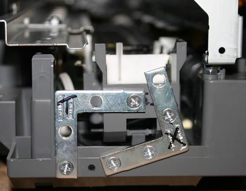
Before installing the print head platform, it is necessary to make small jumpers. I made them from corners that I sawed into 2 parts (see photo above). You can of course make them yourself.


Afterwards, I marked the holes for drilling in the printer. The bottom holes are very easy to mark and drill. Then, I immediately screwed the brackets into place.

The next step is to mark and drill the upper holes in the platform; this is somewhat more difficult to do, because everything should be on the same level. To do this, I placed a pair of nuts in the places where the platform joins the base of the printer. Using a level, make sure the platform is level. We mark the holes, drill and tighten with bolts.


Step 7. “Lifting” the print head cleaning mechanism
When the printer finishes printing, the head is “parked” in the head cleaning mechanism, where the head nozzles are cleaned to prevent them from drying out and clogging. This mechanism also needs to be raised a little.
I secured this mechanism using two corners (see photo above).
Step 8: Feed System
At this stage, we will consider the process of manufacturing the feed system and installing the material feed sensor.

When designing the feed system, the first challenge was installing the material feed sensor. Without this sensor the printer would not function, but where and how to install it? When paper passes through the printer, this sensor tells the printer controller when the beginning of the paper has passed and based on this data the printer calculates the exact position of the paper. The feed sensor is a conventional photosensor with an emitting diode. When paper passes (in our case, material), the beam in the sensor is interrupted.
For the sensor and feed system, I decided to make a platform out of plywood.

As you can see in the photo above, I glued several layers of plywood together in order to make the feed flush with the printer. In the far corner of the platform I attached a feed sensor through which the material will flow. I made a small cutout in the plywood to insert the sensor.


The next task was the need to make guides. To do this, I used aluminum corners, which I glued to the plywood. It is important that all angles are clearly 90 degrees and the guides are strictly parallel to each other. As the feed material, I used an aluminum sheet on which the copper-plated PCB will be placed and fixed for printing.


I made the material supply sheet from an aluminum sheet. I tried to make the sheet size approximately equal to A4 format. After reading a little on the Internet about the operation of the paper feed sensor and the printer in general, I found out that for the printer to work correctly, it is necessary to make a small cutout in the corner of the material feed sheet so that the sensor is triggered a little later than the feed rollers begin to spin. The length of the cutout was about 90mm.

After everything was done, I attached a regular sheet of paper to the feed sheet, installed all the drivers on the computer and made a test print on a regular sheet.
Step 9. Filling the ink cartridge

The last part of the printer modification is dedicated to ink. Regular Epson ink is not resistant to the chemical processes that occur during etching of a printed circuit board. Therefore, you need special ink, they are called Mis Pro yellow ink. However, this ink may not be suitable for other printers (non-Epson), because... other types of printheads may be used there (Epson uses a piezoelectric printhead). The online store inksupply.com offers delivery to Russia.

In addition to ink, I bought new cartridges, although of course you can use old ones if you wash them well. Naturally, to refill the cartridges you will also need a regular syringe. Also, I bought a special device for resetting printer cartridges (blue in the photo).
Step 10. Tests

Now let's move on to printing tests. In the Eagle design program, I made several printable blanks, with tracks of varying thicknesses.


You can evaluate the quality of printing from the photographs above. And below is a video of printing:
Step 11: Etching
For etching boards manufactured using this method, only a ferric chloride solution is suitable. Other etching methods (copper sulfate, hydrochloric acid, etc.) may corrode Mis Pro yellow ink. When etching with ferric chloride, it is better to heat the printed circuit board using a heat gun, this speeds up the etching process, etc. Less “eating” of the ink layer.

The heating temperature, proportions and duration of etching are selected experimentally.


We found out that for this you need a flatbed printer. An industrial flatbed printer costs astronomical money, so most people try to build a flatbed printer with their own hands, which not only saves a lot of money, but, in principle, makes the project real without the need to sell half an apartment to drug dealers for a stash.
In fact, a flatbed printer can serve not only as an addition to directly printing colorful images on finished products. It can act as a completely independent means of production! For example, for printing on T-shirts and fabric (textile printer), printing on tiles and glass (for an interior design studio), for making printed circuit boards in electronics production, and much, much more. Those. as we see, a flatbed printer is a separate business that anyone can start from their first salary, simply by making a flatbed printer with their own hands!
First you need to understand what remaking an inkjet printer involves. A regular inkjet printer is designed to print on paper, but we want to print directly on a hard surface. This means we just need to redo the paper feeding mechanism, instead of which we need to install a movable table with a flat surface to position the object on which direct printing will be done (plywood, wood, T-shirt, tile, glass, phone case, loaf of bread with a memorable inscription, etc. .d.).
The flat table can be driven by the same engine from the paper pulling mechanism, but you need to understand that such a table cannot “drag” anything heavier than a piece of rag under the printer. And the table itself should be made of some kind of “airy” material, for example, plexiglass or plastic, and preferably with holes to lighten the weight. And sometimes for large-format printers it is advisable to move not the table under the printer, but the printer itself above the table! This task is certainly beyond the capabilities of a regular engine!
I believe that you need to leave the original printer motor alone and adapt the stepper motor that is most suitable for the tasks of “heavy lifting”. The choice of stepper motors is so large that you can drag at least half a cubic meter of bricks under the printer and directly print on them. Personally, I am a supporter of versatility and do not like to initially lock myself into the framework of “printing only on fabric,” so I chose the option of converting the inkjet printer into a flatbed printer using an external stepper motor to drive the moving table.
To control a stepper motor you need a controller and a driver. There are no questions with the stepper motor driver - it could be the simplest A4988, costing 180 rubles, which provides an output current to the motor winding of up to 2 Amps (using a radiator and external fan cooling). This is more than enough to control a medium-power stepper motor.
It remains to understand what the controller is needed for and what functions it will perform. If you disassemble any inkjet printer and pay attention to the paper feeding mechanism, you will see a long shaft with rubberized rollers, driven by a small motor through a gear drive. There is also a transparent disk with small black divisions on the shaft - this is the so-called encoder. The encoder disk passes through a black optical sensor, and these divisions on the disk help the printer electronics understand how much the paper feed shaft has rotated, in other words, how much the sheet has moved in the printer. Our controller basically just needs to convert “paper offset” to “table offset.” To do this, he must also “read” the data from the encoder (count the black marks) and convert this data into steps for the stepper motor.
 You can use everyone's favorite Arduino board as a controller. You can buy a simple Arduino for 500 rubles. Someone will say that Arduino is too slow - this is not entirely true, or rather, it is not true at all! Arduino is simply a convenient development environment for Atmel AVR microcontrollers. In the Arduino environment, no one forbids using the “native” commands of this microcontroller instead of the library functions of the Arduino environment, which are really slow. With “native” commands, your microcontroller will operate almost at a clock frequency (which is 16 MHz, stabilized by a quartz resonator on the board). For comparison, the signal from a printer encoder can arrive at a frequency of no more than several hundred hertz or kilohertz, i.e. Our microcontroller will roughly work for 1 clock cycle, and rest for the remaining 1000 clock cycles!
The optical sensor of the printer encoder has two channels (conventionally - A and B). When the encoder disk rotates, rectangular pulses will appear at the output of the optical sensor. The direction of rotation of the encoder disk can be determined by determining from which channel the pulse comes first. If an impulse has arrived in channel A, but there is no impulse yet in channel B, then the disk rotates clockwise (for example); if an impulse has arrived in channel A, and there is already an impulse in channel B, then the rotation goes counterclockwise (again, for example). In a real program, we can then easily change “-” to “+” if it turns out that the motor is spinning in the wrong direction.
The optical sensor is connected to the Arduino via digital inputs D2 and D3 (marked with numbers “2″ and “3″” on the Arduino board, respectively). All that remains is to connect the stepper motor controller based on the A4988 module to the Arduino output. It receives input signals STEP (one step or microstep of a stepper motor) and DIR (direction of rotation: 1 - in one direction, 0 - in the other). On Arduino, for the STEP and DIR outputs, we can assign any pins we like, for example, 12 and 13. On the 13th pin, there is usually also an LED directly on the Arduino board, which will also give us visual confirmation of the transfer of STEP steps to the stepper motor driver . If you want, you can hang DIR on pin 13, then the LED will light up when rotated in one direction and go out when rotated in the other - also visually.
The program for the microcontroller is very simple. Here's its listing:
// Pins for encoder input
#define ENC_A_PIN 2
#define ENC_B_PIN 3
// Read value from encoder
#define ENC_A ((PIND & (1<< ENC_A_PIN)) > 0)
#define ENC_B ((PIND & (1<< ENC_B_PIN)) > 0)// STEP/DIR pins
#define STEP_PIN 13
#define DIR_PIN 12// Sending data to STEP/DIR ports
#define STEP(V) (PORTB = V ? PORTB | (1<< (STEP_PIN-8)) : PORTB & (~(1<<(STEP_PIN-8))))
#define DIR(V) (PORTB = V ? PORTB | (1<< (DIR_PIN-8)) : PORTB & (~(1<<(DIR_PIN-8))))void setup() (
intSetup();
driveSetup();
}void driveSetup())(
pinMode(STEP_PIN, OUTPUT);
STEP(0);pinMode(DIR_PIN, OUTPUT);
DIR(0);
}volatile boolean A, B;
void intSetup())(
pinMode(ENC_A_PIN, INPUT);
A = ENC_A;
attachInterrupt(0, onEncoderChannelA, CHANGE);pinMode(ENC_B_PIN, INPUT);
B = ENC_B;
attachInterrupt(1, onEncoderChannelB, CHANGE);
}volatile unsigned long pulses = 0;
volatile boolean gotDir = false;
volatile boolean cw = false;unsigned long pps = 2; // pulses per step
if(pulses >= pps)(
pulses = 0;
STEP(1);
delayMicroseconds(10);
STEP(0);
}if(gotDir)(
DIR(!cw);
gotDir = false;
}
}void onEncoderChannelA())(
if((A && B) || (!A && !B))(
if(!cw) gotDir = true;
cw = true;
)else(
if(cw) gotDir = true;
cw = false;
}pulses++;
}void onEncoderChannelB())(
if((B && A) || (!B && !A))(
if(cw) gotDir = true;
cw = false;
)else(
if(!cw) gotDir = true;
cw = true;
}pulses++;
}
A few explanations about the code. In attachInterrupt() we attach a handler function to an external interrupt, which is triggered by a change in the state of the encoder optical sensor channel. Any change from 0 to 1 and 1 to 0 is monitored by the function onEncoderChannelA and onEncoderChannelB for channel A and B respectively. Well, then we simply count the number of pulses from the encoder and issue STEP and DIR commands to the stepper motor. As you can see, nothing complicated!
Then, depending on the design of the table and the transmission mechanism, it will be necessary to select the coefficient for converting pulses from the encoder into motor steps. In my program, this value is set in the variable pps (pulses per step - pulses per step).
The video shows a mock-up of a controller for a flatbed printer table in action. For now, a linear encoder is used instead of a circular one, but this does not change the essence. You can see how the controller controls the position of the stepper motor in real time depending on the position of the encoder sensor.
The article describes the process of manufacturing a flatbed printer from their Epson 3880 printer.
1)Preparing the printer.
1.1) What will be required?
1. A set of screwdrivers (electric screwdriver, screwdriver for convenience)
2. Angle grinder (grinder)
3. Drill, metal drills
4. Pliers.
Disassembling the printer
We begin preparing the printer for conversion into a textile printer by completely disassembling the device.
Ours is Epson Stylus Pro 3880
First, remove all the plastic casing of the printer.
Remove the control panel and disconnect the cable. 
We remove the side plastic covers, they are latched. 

Removing the front plastic panel 
Removing the upper part of the case
Removing the paper feed tray


Disconnect the waste ink tank presence sensor
(diaper), we won't need it anymore 
Remove all front paper output trays 


Removing the back of the case


Unscrew and remove the paper feed motor 
Unscrew the paper pickup roller mounting brackets 


Unscrew the screws securing the paper feed unit 


And we take it off 
Removing the protective plastic panels 


Below them we see a compartment for the formatter board and power supply 
Remove the top cover of the compartment 
And disconnect all connectors and cables from the formatter board 

Printer modification
First you need to remove all unnecessary components and parts.
We need to completely remove the paper feeding mechanism; we don’t have to feel too sorry for it; we won’t need it anymore.


And we take it off


Removing the plastic panel

and paper pulling shafts, as well as the encoder disk drive shaft


View from below

We will no longer need the paper feed shafts, but the encoder disk drive shaft needs to be cut off immediately behind the locking ring and put in place, so do not lose the spring, washer and locking ring.


We’ll also remove the fastening of the mechanism of the front paper trays, it doesn’t really interfere, but we won’t need it for anything either


Now turn the printer on its side so that there is access to the print head. We are interested in the plastic cover under which the optocouplers are located


There are two of them. We need to remove the one that is smaller in size


The removed optocoupler will no longer be needed

Now you need to attach the case that contains the motherboard and power supply to the top of the printer, so that in the future it does not interfere with the passage of the moving part of the table


To do this, take the upper part of the body and, placing it in place, mark and drill holes for the bolts


Screw on the housing cover


It should work out like this

Install the lower part and connect the connectors and cables


You don’t have to tighten the screws for now, as we will still need access to the formatter to connect the table control board
Remove the metal cross member. It will also interfere with the passage of the moving part of the table


Another metal crossbar at the bottom of the printer frame will interfere with the table; to remove it we will have to use a grinder


From the bottom plastic part of the case we make legs for our printer. One of them will contain a container for waste ink (diaper)


The width of the legs should not be wider than the front plastic panel of the case


Connecting the table control board
After the modification of our printer is almost completed, we need to connect the table control board

The installation kit for the table control board contains two wires with connectors and two cables.
Let's start with the wires. Connect to the control board and the motherboard


Connect the connector marked CN54 to the connector on the printer motherboard; it is also marked CN54. The wire block does not fit the connector on the motherboard, but it’s not scary; carefully unbend the connector and connect the wire.
Important!
On the motherboard, the connector has 4 pins, and the wire has 3. We need to connect the wire, as in the photo, so that the right pin of the connector remains unused


And to the printer motherboard. The connector is also marked CN53. There are no more problems here; the block fits the connector on the motherboard. Here, too, the right contact of the connector should remain unused.

It remains to connect two cables

One of them is connected to the connector on the table control board marked CN49. On the printer motherboard, this cable is connected to a connector also marked CN49

The second cable, connected to the connector on the table control board labeled PF Sensor, is connected to the connector on the optocoupler of the encoder disk.


The original printer cable that goes to this sensor can be removed completely; we don’t need it.
Connected table control board

We also need to slightly modify our printer motherboard, namely, install jumpers (jumpers) in certain contacts on the board. As shown in the photo.
All that remains is to connect the cable to the contact pad to determine the diaper chip. It is located on the right foot of the printer. Connects in the same way as it was connected before disassembly, using a standard printer cable


Printer assembly
We install the legs cut from the bottom of the printer into place.

You need to cut off the back part from the top of the body


Since the raised compartment with the motherboard and power supply will not allow it to fall into place, it should turn out like this:

After this we install the upper part of the body


Installing the side covers


We connect the cable to the control panel and install it in place


At this point, the conversion of our printer is almost complete; all that remains is to refill and install the cartridges with special ink for direct printing on textiles. Bleed the internal ink supply system to fill the ink supply loops, as well as the print head dampers.
The last step will be connecting our prepared printer and a ready-made table for direct printing.